Instalación del Firmware AREDN®
Los pasos para instalar el firmware en un dispositivo están documentados en el sitio web de AREDN® en la sección Current Software. En el menú Software, seleccione Download para acceder a la página Current Software.
Hay dos casos para instalar el firmware AREDN®:
- Si ya tiene una versión de firmware de AREDN® ejecutándose en su dispositivo, puede usar la interfaz web de su computadora para navegar a Setup > Administration > Firmware Update para instalar su nuevo firmware. Este proceso se explicará con más detalle en la sección Configuración Avanzada de esta guía. Para obtener información adicional vea también Consejos de Actualizacióón de Firmware en la sección Guías Prácticas.
Si está instalando el firmware AREDN® en un dispositivo por primera vez, cada plataforma de hardware puede requerir un procedimiento único.
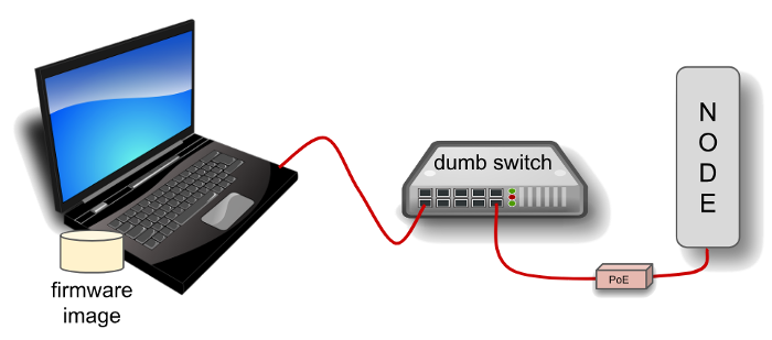
El diagrama anterior muestra que su ordenador con la imagen de firmware descargada debe estar conectado al nodo mediante cable Ethernet para instalar la imagen AREDN®. Es Útil conectar ordenador y nodo a través de un simple switch Ethernet para que éste pueda mantener el enlace con el ordenador mientras se reinicia el nodo.
Nodos con diferente hardware requerirán métodos diferentes para instalar el firmware AREDN®. Para los dispositivos Ubiquiti, el cliente TFTP de su computadora se conectará al servidor TFTP del nodo para cargar la imagen del firmware. Para los dispositivos TP-LINK y GL-iNET, el navegador web de su ordenador se conectará al servidor web del nodo para cargar la imagen del firmware. Para los dispositivos Mikrotik, su ordenador ejecutará un servidor de arranque remoto y el cliente de arranque remoto del nodo cargará su imagen de arranque desde su computadora. Consulte los procedimientos específicos a continuación para el hardware de su nodo.
Ubiquiti First Install Process
Ubiquiti devices have a built-in TFTP server to which you can upload the AREDN® factory image. Your computer must have TFTP client software available. Linux and Mac both have native TFTP clients, but you may need to enable or obtain a TFTP client for Windows computers. If you are using a Windows computer, enable the TFTP client or download and install another standalone TFTP client of your choice.
Different TFTP client programs may have different command line options or flags that must be used, so be sure to study the command syntax for your TFTP client software. The example shown below may not include the specific options required by your client program.
Download the appropriate factory file for your device by following the instructions in the Downloading AREDN Firmware section of this documentation.
- Set your computer’s Ethernet network adapter to a static IP address that is a member of the correct subnet for your device. Check the documentation for your specific hardware to determine the correct network number. As in the example below, most Ubiquiti devices have a default IP address of 192.168.1.20, so you can give your computer a static IP on the 192.168.1.x network with a netmask of 255.255.255.0. For example, set your Ethernet adapter to a static IP address of 192.168.1.100.
You can choose any number for the fourth octet, as long as it is not the same as the IP address of the node. Of course you must also avoid using 192.168.1.0 and 192.168.1.255, which are reserved addresses that identify the network itself and the broadcast address for that network. Other devices may have different default IP addresses or subnets, so select a static IP for your computer which puts it on the same subnet but does not conflict with the default IP of the device.
- Connect an Ethernet cable from your computer to the dumb switch, and another cable from the LAN port of the PoE adapter to the switch.
- Put the Ubiquiti device into TFTP mode by holding the reset button while plugging your node’s Ethernet cable into the POE port on the PoE adapter.
- Continue holding the device’s reset button for approximately 30 to 45 seconds until you see the LEDs on the node alternating in a 1-3, 2-4, 1-3, 2-4 pattern, then release the reset button.
- Open a command window on your computer and execute a file transfer command to send the AREDN firmware to your device. Target the default IP address of your Ubiquiti node, such as 192.168.1.20 or 192.168.1.1 for AirRouters. The following is one example of TFTP commands that transfer the firmware image to a node:
>>>
[Linux/Mac]
> tftp 192.168.1.20
> bin                 [Transfer in "binary" mode]
> trace on            [Show the transfer in progress]
> put <full path to the firmware file>
  [For example, put /temp/aredn-3.19.3.0-ubnt-nano-m-xw-factory.bin]
-----------------------------------
[Windows with command on a single line]
> tftp -i 192.168.1.20 put C:\temp\aredn-3.19.3.0-ubnt-nano-m-xw-factory.bin
The TFTP client should indicate that data is being transferred and eventually completes.
- Watch the LEDs for about 2-3 minutes until the node has finished rebooting. The reboot is completed when the LED 4 light (farthest on the right) is lit and is steady green.
- Configure your computer’s Ethernet network interface to use DHCP for obtaining an IP address from the node. You may need to unplug/reconnect the Ethernet cable from your computer to force it to get a new IP address from the node.
- After the node reboots, open a web browser and enter the following URL:
http://localnode.local.meshSome computers may have DNS search paths configured that require you to use the fully qualified domain name (FQDN) to resolve localnode to the mesh node’s IP address. - Navigate to the Setup page and configure the new “firstboot” node as described in the Basic Radio Setup section.
TP-LINK First Install Process
Preferred Process
TP-LINK devices currently allow you to use the manufacturer’s pre-installed PharOS web browser user interface to upload and apply new firmware images. This is the most user-friendly way to install AREDN® firmware. Navigate to the Setup section to select and upload new firmware. Check the TP-LINK documentation for your device if you have questions about using their built-in user interface.
Alternate Process
TP-LINK devices also have a built-in TFTP and Bootp client which allows them to obtain new firmware from an external source. Your computer must run a TFTP/Bootp server in order to provide firmware images to the node. In certain situations you may need to use this method to update the firmware or to restore a TP-LINK recovery file by following the steps below.
Preparation
- Download the appropriate TP-LINK factory file and rename this file as
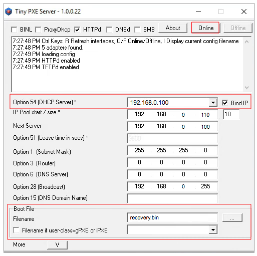
recovery.bin - Set your computer’s Ethernet network adapter to a static IP address that is a member of the correct subnet for your device. Check the documentation for your specific hardware to determine the correct network number. As in the example below, most TP-LINK devices use the 192.168.0.x subnet by default, so you can give your computer a static IP such as 192.168.0.100 with a netmask of 255.255.255.0.
You can choose any number for the fourth octet, as long as it is not the same as the IP address of the node and is not within the range of DHCP addresses you will be providing in step 2 below. Of course you must also avoid using 192.168.0.0 and 192.168.0.255, which are reserved addresses that identify the network itself and the broadcast address for that network. Other devices may have different default IP addresses or subnets, so select a static IP for your computer which puts it on the same subnet.
- Connect an Ethernet cable from your computer to the dumb switch, and another cable from the LAN port of the PoE adapter to the switch.
Linux Procedure
- Create a directory on your computer called
/tftpand copy the TP-LINKrecovery.binfile there. - Determine your computer’s Ethernet interface name with
ifconfig. It will be the interface you set to 192.168.0.100 above. You will use this interface name in the command below as the name after-iand you must substitute your login user name after-ubelow. Use adhcp-rangeof IP addresses that are also on the same subnet as the computer: for example 192.168.0.110,192.168.0.120 as shown below. - Become
rootand open a terminal window to execute the following dnsmasq command:
>>>
(root)# dnsmasq -i eth0 -u joe --log-dhcp --bootp-dynamic \
      --dhcp-range=192.168.0.110,192.168.0.120 -d -p0 -K \
      --dhcp-boot=recovery.bin --enable-tftp --tftp-root=/tftp/
- With the PoE unit powered off, connect an Ethernet cable from the TP-LINK node to the POE port.
- Push the reset button on the TP-LINK and hold it while powering on the PoE unit. Continue to hold the reset button until you see output information from the computer window where you ran the dnsmasq command, which should happen after about 10 seconds. Release the reset button as the computer starts communicating with the node. When you see the “sent” message, this indicates success, and the TP-LINK node has downloaded the image and will reboot. You can now <ctrl>C or kill dnsmasq.
Windows Procedure
You will need Tiny PXE software on your Windows computer. Download this software and extract it on your computer.
- Navigate to the folder where you extracted the Tiny PXE software and edit the
config.inifile. Directly under the[dhcp]tag, add the following line:rfc951=1then save and close the file. - Copy the
recovery.binfirmware image into thefilesfolder under the Tiny PXE server directory location. - Start the Tiny PXE server exe and select your Ethernet interface IP from the dropdown list called
Option 54 [DHCP Server], making sure to check theBind IPcheckbox. Under the “Boot File” section, enterrecovery.bininto the the Filename field, and uncheck the checkbox for “Filename if user-class = gPXE or iPXE”. Click the Online button at the top of the Tiny PXE window.
- With the PoE unit powered off, connect an Ethernet cable from the TP-LINK node to the POE port. Press and hold the reset button on the node while powering on the PoE unit.
- Continue holding the reset button until you see
TFTPd: DoReadFile: recovery.binin the Tiny PXE log window. - Release the node’s reset button and click the Offline button in Tiny PXE. You are finished using Tiny PXE when the firmware image has been read by the node.
Final Configuration Steps
- Configure your computer’s Ethernet network interface to use DHCP for obtaining an IP address from the node.
- After the node reboots, open a web browser and enter the following URL:
http://localnode.local.meshSome computers may have DNS search paths configured that require you to use the fully qualified domain name (FQDN) to resolve localnode to the mesh node’s IP address. - Navigate to the Setup page and configure the new “firstboot” node as described in the Basic Radio Setup section.
Mikrotik First Install Process
Mikrotik devices must be flashed using steps that are similar to the alternate TP-LINK process described above. Your computer must run a TFTP/Bootp server in order to provide firmware images to Mikrotik nodes. Mikrotik nodes require a two-part install process: First, install and boot the correct mikrotik-vmlinux-initramfs file with the elf extension, and then use the in-memory-only AREDN® Administration UI to complete the installation of the appropriate mikrotik-rb file with the bin extension.
Preparation
- Download the appropriate Mikrotik elf and bin files. Rename the elf file to
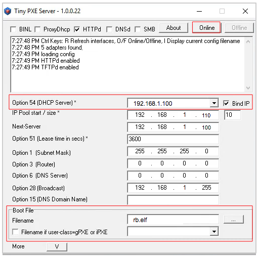
rb.elfand keep the bin file available for later. - Set your computer’s Ethernet network adapter to a static IP address that is a member of the correct subnet for your device. Check the documentation for your specific hardware to determine the correct network number. As in the example below, most Mikrotik devices use the 192.168.1.x subnet by default, so you can give your computer a static IP such as 192.168.1.100 with a netmask of 255.255.255.0.
You can choose any number for the fourth octet, as long as it is not the same as the IP address of the node and is not within the range of DHCP addresses you will be providing in step 2 below. Of course you must also avoid using 192.168.1.0 and 192.168.1.255, which are reserved addresses that identify the network itself and the broadcast address for that network. Other devices may use different default subnets, such as QRT units which use 192.168.88.x. Select a static IP for your computer which puts it on the same subnet as your device.
- Connect an Ethernet cable from your computer to the dumb switch, and another cable from the LAN port of the PoE adapter to the switch. If you are flashing a Mikrotik hAP ac lite device, connect the Ethernet cable from Port 1 of the Mikrotik to the dumb switch.
Linux Procedure
- Create a directory on your computer called
/tftpand copy therb.elffile there. - Determine your computer’s Ethernet interface name with
ifconfig. It will be the interface you set to 192.168.1.100 above. You will use this interface name in the command below as the name after-iand you must substitute your login user name after-ubelow. Use adhcp-rangeof IP addresses that are also on the same subnet as the computer: for example 192.168.1.110,192.168.1.120 as shown below. - Become
rootand open a terminal window to execute the following dnsmasq command:
>>>
(root)# dnsmasq -i eth0 -u joe --log-dhcp --bootp-dynamic \
      --dhcp-range=192.168.1.110,192.168.1.120 -d -p0 -K \
      --dhcp-boot=rb.elf --enable-tftp --tftp-root=/tftp/
- With the PoE unit powered off, connect the Mikrotik node to the POE port. Press and hold the reset button on the Mikrotik while powering on the PoE unit or the hAP device.
- Continue to hold the reset button until you see output information from the computer window where you ran the dnsmasq command, which should happen after about ten seconds. Release the reset button as the computer starts communicating with the node. When you see the “sent” message, this indicates success, and the node has downloaded the image and will reboot. You can now <ctrl>C or kill dnsmasq.
Windows Procedure
You will need Tiny PXE software on your Windows computer. Download this software and extract it on your computer.
- Navigate to the folder where you extracted the Tiny PXE software and edit the
config.inifile. Directly under the[dhcp]tag, add the following line:rfc951=1then save and close the file. - Copy the
rb.elffile into thefilesfolder under the Tiny PXE server directory location. - Start the Tiny PXE server exe and select your Ethernet interface IP from the dropdown list called
Option 54 [DHCP Server], making sure to check theBind IPcheckbox. Under the “Boot File” section, enterrb.elfinto the the Filename field, and uncheck the checkbox for “Filename if user-class = gPXE or iPXE”. Click the Online button at the top of the Tiny PXE window.
- With the PoE unit powered off, connect the Mikrotik node to the POE port. If you are flashing a Mikrotik hAP ac lite device, connect the LAN cable from Port 1 of the Mikrotik to the dumb switch.
- Press and hold the reset button on the node while powering on the PoE unit or the device. Continue holding the reset button until you see
TFTPd: DoReadFile: rb.elfin the Tiny PXE log window. - Release the node’s reset button and click the Offline button in Tiny PXE. You are finished using Tiny PXE when the firmware image has been read by the node.
Final Configuration Steps
After booting the AREDN firmware image the node should have a default IP address of 192.168.1.1. Change your computer’s Ethernet interface to DHCP mode to obtain an IP address from the node. For the hAP ac lite, pull the Ethernet cable from the WAN port (1) on the Mikrotik and insert it into one of the LAN ports (2,3,4). You should be able to ping the node at 192.168.1.1. If this does not work, then something is wrong. Don’t proceed until you can ping the node. You may need to disconnect and reconnect your computer’s network cable to ensure that your IP address has been reset. Also, you may need to clear your web browser’s cache in order to remove cached pages remaining from your node’s previous firmware version.
In a web browser, open the node’s Administration page
http://192.168.1.1/cgi-bin/admin(user = ‘root’ password = ‘hsmm’) and navigate to the Setup > Administration > Firmware Update section. Select the bin file you previously downloaded and click the Upload button.As an alternative to using the node’s web interface, if your node has plenty of free memory you can copy the bin file to the node and run a command line program to install the image. This will allow you to see any error messages that are not displayed when using the web interface upgrade procedure. Execute the following commands from your computer:
>>>
my-computer:$ scp -P 2222 aredn-firmware-filename.bin root@192.168.1.1:/tmp
my-computer:$ ssh -p 2222 root@192.168.1.1
~~~~~~~ after logging into the node with ssh ~~~~~~~
node:# sysupgrade -n /tmp/aredn-firmware-filename.bin
After the node reboots, navigate to the node’s Setup page and configure the new “firstboot” node as described in the Basic Radio Setup section.
GL-iNET First Install Process
GL-iNET devices allow you to use the manufacturer’s pre-installed OpenWRT web interface to upload and apply new firmware images. Check the GL-iNET documentation for your device if you have questions about initial configuration. Both GL-iNET and AREDN devices provide DHCP services, so you should be able to connect your computer and automatically receive an IP address on the correct subnet. GL-iNET devices have a default IP address of 192.168.8.1, so if for some reason you need to give your computer a static IP address you can use that subnet.
After the GL-iNET device has been booted and configured, navigate to the Upgrade section and click Local Upgrade to select the AREDN® “sysupgrade.bin” file you downloaded for your device. Be sure to uncheck/deselect the “Keep Settings” checkbox, since GL-iNET settings are incompatible with AREDN. After the device has rebooted to the AREDN® image, you should be able to navigate to http://192.168.1.1 for the firstboot or NOCALL page to appear.
If for some reason your GL-iNET device gets into an unusable state, you should be able to recover using the process documented here: GL-iNET debrick procedure
Troubleshooting Tips
One common issue can occur when installing firmware using a web browser interface. The browser cache stores data for the URLs that have been visited, but IP addresses and other parameters often change during the install process. It is possible for the cache to contain information that doesn’t match the latest settings for the URL, so the browser may block the connection setup and display an ERR_CONNECTION_RESET message. Clearing the web browser’s cache will allow the latest URL settings to be registered so you can continue with the install process.
Instead of a Connection Reset message, sometimes a Bad Gateway message may appear. This is an HTTP Status Code that can mean any of several things. Often it indicates a network communication issue between a web browser and a web server. During AREDN® firmware installs you can usually resolve a Bad Gateway issue by doing one or more of the following things:
- Refresh or Reload the URL for your node.
- Clear your browser cache and delete cookies.
- Close your browser and restart a new session.
- Use a different web browser program or a Safe Mode / Incognito browser window.
- Unplug and reconnect the Ethernet cable from your computer to ensure that your machine has received a new DHCP IP address on the same subnet as the node’s updated IP.
If for some reason the node’s web interface does not work, you may be able to use a command line program to install the firmware image. You must first copy the firmware bin file to the node, then log into the node and use the sysupgrade program to install the image as illustrated below.
>>>
my-computer:$ scp -P 2222 aredn-firmware-filename.bin root@192.168.1.1:/tmp
my-computer:$ ssh -p 2222 root@192.168.1.1
~~~~~~~ after logging into the node as root (hsmm) ~~~~~~~
node:# sysupgrade -n /tmp/aredn-firmware-filename.bin
Additional questions and troubleshooting assistance can usually be obtained by creating a post on the AREDN® online forum, which has an active community of helpful and experienced operators.
Post-Install Steps
Once your device is running AREDN® firmware, you can display its web interface by connecting your computer to the LAN port on the PoE and navigating to the following URL: http://localnode.local.mesh Some computers may have DNS search paths configured that require you to use the fully qualified domain name (FQDN) to resolve localnode to the mesh node’s IP address. Each node will serve its web interface on both port 80 and 8080.
By default AREDN® devices run the DHCP service on their LAN interface, so your computer will receive an IP address from the node as soon as it is connected with an Ethernet cable. Ensure that your computer is set to obtain its IP address via DHCP. You may also need to clear your web browser’s cache in order to remove cached pages remaining from your node’s previous firmware version.